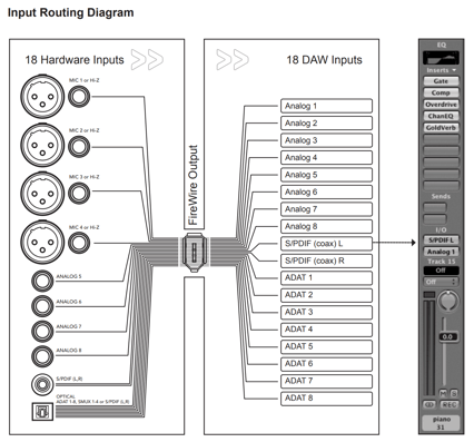
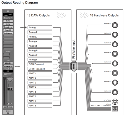
Unless routing is modified in Maestro software, all Ensemble rear panel inputs are routed via Firewire to the Mac, while all rear panel outputs are routed via Firewire from the Mac, as depicted on the next two pages.
Input Routing Diagram
Output Routing Diagram
Maestro 2
Routing
The input and output routing control is accomplished across a combination of routing grids. With this release of Maestro 2 software, it is now possible to route individual stereo pairs from hardware inputs directly to hardware outputs while also routing other pairs through a DAW or other software. Audio Routing is accomplished using the following three routing grids:
- Standalone Routing - Route Ensemble hardware inputs to hardware outputs.
- Input Routing - Route Ensemble hardware inputs to Mac audio software inputs.
- Output Routing - Route Mac audio software outputs to Ensemble hardware outputs.
When using these routing grids, hardware outputs may only have one source, either a hardware input or a software output. Thus, once a hardware output is assigned in either the Standalone or Output Routing grid, it is removed from the other grid. Each pair of Ensemble hardware outputs may be freely routed in either the Standalone or Output Routing grid.
To route a mix of hardware inputs and software outputs to a hardware output, use Ensemble’s low latency mixer in the Mixer tab window.
Input Routing
The Input Routing tab window determines how Ensemble hardware inputs are routed to audio software inputs.
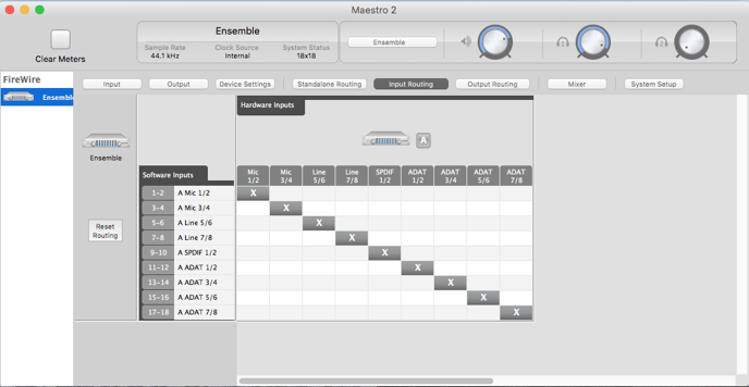
1. Hardware Inputs Columns - The hardware analog and digital inputs of the Ensemble are displayed in these columns.
2. Software Inputs Rows - Available audio software inputs are displayed in these rows in pairs (1-2, 3-4, etc).
3. Software Input Labels - Once a connection has been made between hardware and software inputs, the software input label (consisting of the peripheral prefix plus the hardware input label) appears in these fields. For these labels to appear in your audio software input/output assignments, ensure that the software is set to accept labels transmitted through Ensemble’s Core Audio driver.
4. Reset Routing - This button will reset the Input Routing assignments to the default settings.
Audio connections between hardware and software inputs are made by positioning markers on the routing grid at the intersection of the desired hardware and software channels. By default, hardware inputs are routed sequentially to software inputs. Note that the movement of the markers is restricted based on the routing capability of the system. On the Input Routing page, one hardware input may be assigned to multiple software inputs (in effect splitting the signal) but multiple hardware inputs may not be assigned to one software input (an operation which would require the summing of input signals). Each marker’s range of motion is indicated by the horizontal shading as depicted above by arrows on the Input routing grid.
Output Routing
The Output Routing tab window determines how audio software outputs are routed to Ensemble hardware outputs.
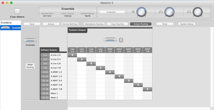
1. Hardware Outputs Columns - The hardware analog and digital outputs of the Ensemble are displayed in these columns.
2. Software Output Rows - Available audio software outputs are listed in these rows in pairs (1-2, 3-4, etc).
3. Mixer Output Rows - The two low latency mixer outputs appear at the bottom of the Software Outputs list, and may be assigned to one or more hardware output pairs.
4. Software Output Labels - Once a connection has been made between software and hardware outputs, the soft- ware output label (consisting of the peripheral prefix plus the hardware output label) appears in these fields.
5. Reset Routing - This button will reset the Output Routing assignments to the default settings. In this case it will also remove any routing assignments that have been made in the Standalone Routing page. See Standalone Routing for more info.
Manipulation of the Output Routing Tab Window is essentially the same as the Input Routing Tab Window, with the important distinction that one software output may be assigned to multiple hardware outputs but multiple software outputs may not be assigned to one hardware output. Each marker’s range of motion is indicated by the vertical shading as depicted above by arrows on the Output routing grid.
Note that each marker represents an odd/even pair of audio signals - it’s not possible to route the odd and even signal of a pair to different destinations.
Standalone Routing
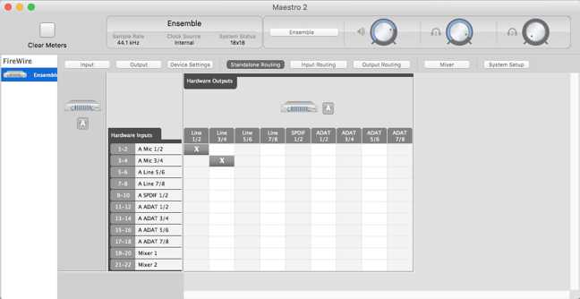
1. Hardware Output Columns - The hardware analog and digital outputs of the Ensemble are displayed in these columns.
2. Hardware Input Rows - The hardware analog and digital inputs of the Ensemble are displayed in these rows.
3. Mixer Output Rows - The two low latency mixer outputs appear at the bottom of the Hardware Inputs list, and may be assigned to one or more hardware output pairs.
Audio connections between hardware inputs and outputs are made by positioning markers on the routing grid at the intersection of the desired hardware input and output. Similar to the Input and Output Routing grids marker movement is restricted based on the routing capability of the system. One hardware input may be assigned to multiple hardware outputs (in effect splitting the signal) but multiple hardware inputs may not be assigned to one hardware output (an operation which would require the summing of input signals).
Each marker’s range of motion is indicated by the vertical shading on the routing grid, as depicted above by arrows on the Standalone routing grid.