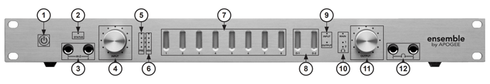
1. Power Switch – Press this button to apply power to Ensemble. When Ensemble’s AC input is connected, the switch will light dimly to indicate that the unit is in Standby.
2. STATUS LED – This multi–color LED provides a quick visual indication of the status of various parameters. • A solid blue LED indicates that Ensemble is locked to the clock source chosen in software control and that the Firewire connection is valid. • A flashing LED indicates that Ensemble is not locked to the selected clock source. • A red Status LED indicates that Ensemble has not achieved a valid Firewire connection. After a few moments Ensemble will switch to Stand-Alone mode. • A green LED indicates that no Firewire connection is present, and that Ensemble is operating in Stand-Alone mode. • A flashing red LED indicates that both error conditions are present.
3. HI–Z Input 1–2 – These 1/4 inch connectors accept high impedance sources such as keyboards and guitars. When a jack is inserted in a Hi–Z connector, the input’s XLR connector is disabled.
4. INPUT Encoder Knob – When inputs 1–4 are set to Mic using software control, this knob controls the mic pre gain; To select the input being controlled, press the encoder knob until the desired PRE LED lights ; turn the encoder clockwise to increase level or counter–clockwise to decrease level. The LEDs encircling the encoder knob indicate the “position” of the knob, providing a quick visual indication of level in the same fashion as a traditional knob. If no inputs are set to Mic in software control, the en- coder has no function.
5. PRE LEDs – These LEDs indicate the selected channel in conjunction with the INPUT encoder knob.
6. 48V LEDs – These LEDs indicate that 48 volt phantom power has been engaged in software control.
7. Meters 1–8 – These meters display either analog inputs or analog outputs, as set in software control.
8. Meters D1,D2 – Meter D1 displays the presence of signal on either channel of the S/PDIF Coax I/O, meter D2 displays the presence of signal on any channel of the Optical I/O.
9. INPUT, OUTPUT LEDs – These LEDs indicate if meters are displaying input or output signals, as set in software control.
10. MAIN, Phones 1,2 LEDs – These LEDs indicate the selected output to be modified by the OUTPUT encoder knob.
11. OUTPUT Encoder Knob – This knob controls the level of the selected output as indicated by the MAIN, hp1 and hp2 LEDs. Operation is similar to that of the Input encoder knob as described above. If Main is set to None in software control, the encoder knob has no effect on the Main outputs.
12. Headphones 1,2 – These TRS connectors provide headphone outputs