General Installation Information
Installing the Second (top) Card Video
Installing the 8Mic Pre module (top) Card Video
Installing I/O Modules
In most cases, Symphony I/O ships with the first I/O Module installed. For the infrequent case where no I/O Modules are installed, this section describes both how to install the first I/O Module as well as a second I/O Module.
Symphony I/O 1st Module Installation Video
Symphony I/O MkII 1st Module Installation Video
Directions
When installing a Mic Pre I/O module, first install an 8x8 or 16 Input I/O Module in the lower slot, then install the Mic Pre I/O Module as described starting with Step 12.
1. Discharge Residual Electricity- IMPORTANT! Even when Symphony I/O is powered off but connected to the AC wall socket, voltages remain active throughout the system. Manipulating circuit boards under these conditions may result in permanent damage.
a. Turn Symphony I/O off, but leave the AC cable connected
b. Ground yourself by touching the front panel of Symphony I/O to discharge static electricity
c. Unplug the AC cable from Symphony I/O
d. Wait for at least 2 minutes to let the power discharge from the circuitry
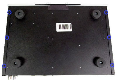
2. Use a Phillips screwdriver to remove the 11 screws holding the cover on. 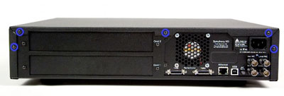
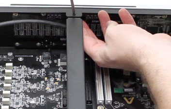
3. To remove the cover, slide it straight back until the underside clips prevent further movement. Then grasp the cover's side panels and gently bow the cover until the bottom lip is free. 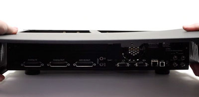
4. Remove the 2 screws holding the center support in place, and lift out the support. 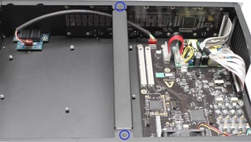
5. Remove both I/O Module blanking panels and set the screws aside for later use. 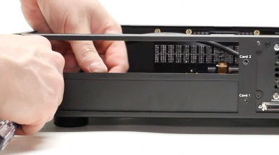
6. Remove the 9 screws indicated below, and set them aside for later use. 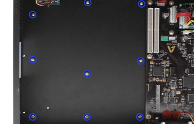
7. Place the first I/O Module into the chassis by inserting the I/O Module rear panel into the Symphony I/O Card 1 opening, then gently dropping the front of the I/O Module into place. Line up the I/O Module's mounting holes with the 9 nuts on the bottom of the chassis. 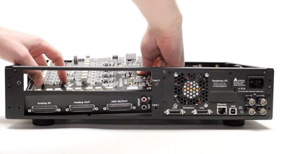
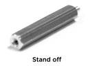
8. Secure the I/O Module by installing the 9 screws removed in Step 6. If you're installing a second I/O Module, install 9 stand-offs in the place of the 9 screws. 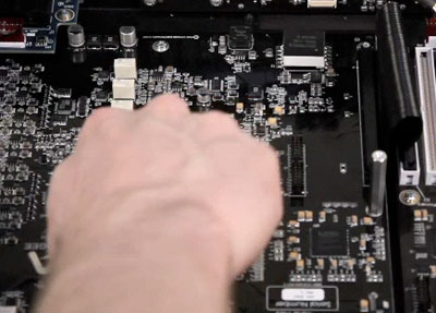
9. Secure the I/O Module rear panel to the chassis rear panel using the two screws from Step 4.
10. If you are only installing a single Module, replace the second slot's blanking panel.
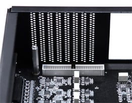
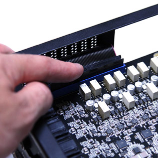
11. Connect the provided ribbon cable between J1 on the Main board and J1 on the I/O Module. Be sure to align the key on each ribbon cable connector to the key slot on each receptacle. 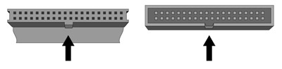

12. When installing a Mic Pre I/O Module, first remove the Input Bridging Jumper from the lower I/O Module, and connect the Mic Pre IO Module's 50-pin ribbon cable to the now-empty socket.
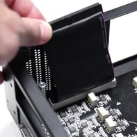
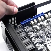
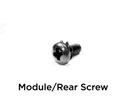
13. To install a second Module, insert the I/O Module rear panel into the Symphony I/O Card 2 opening, then gently dropping the front of the I/O Module into place. Line up the second I/O Module's mounting holes with the tops of the 9 stand-offs, and install 9 module screws.
14. If you are installing a Mic Pre I/O Module, connect the Mic Pre IO Module's 50-pin ribbon cable to the Mic Pre IO Module
15. Connect the provided ribbon cable between J2 on the Main board and J1 on the second I/O Module. Make sure that the lower Module ribbon cable is nested into the upper Module ribbon cable as shown below.
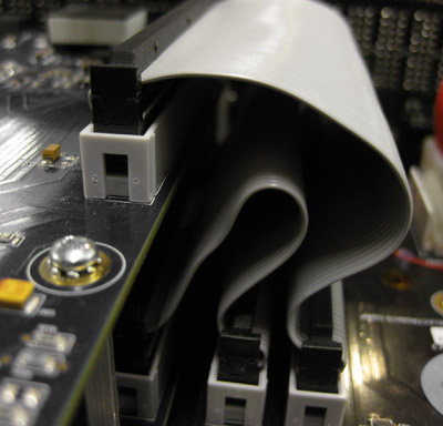
 Do not tuck the Primary I/O ribbon cable underneath the second Module or it could become frayed.
16. Reconnect the center support bar.
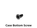
17. Reversing the steps to remove the cover, slide it back into place and secure with the 11 screws removed in Step 2. Use 6 undercut screws to secure the cover bottom and 5 round head screws to secure the cover's rear tab.
Mic Preamp Install video
Symphony I/O 2nd Module Install video
Symphony I/O MkII 2nd Module Install Video